Some fifty years ago, after I had established (to my satisfaction at least) that Bessler’s claim to have invented a perpetual motion machine was genuine, I decided to obtain as many verifiable facts pertaining to the legend of Bessler’s wheel as possible. I believe that my publications below provide a summary of all the information available, but I should mention that I have made considerable progress in deciphering some of the inventor’s coded information, none of this is in the books detailed below, but you visit some of my other websites which give plenty of details. This information is alluded to several times in his books, but it has taken many years of careful study to make sense of only some of it. Having said that there is considerable speculation about the various ciphers embedded in his works but most are too speculative to accept.
I think that the more we speculate the more confusion we can add. Speculation can be taken as fact and if further ideas are added that can compound the problem. I’m not promoting my books as the ultimate source of information on Bessler because there are so many historical documents which remain unexplored due to their poor condition or because they are lost in numerous private libraries. But for now they provide a quick and easy source of information on Johann Bessler and his perpetual motion machine.
Even though I published my biography of Johann Bessler several years ago, the information in it has not altered, because it is based on old documents written more than 300 years ago. There are new additional facts which need to be added at some point but they are details about his later life and although of interest do not impinge on the history of his perpetual motion machine. There are also Bessler’s own books which he published which cover his life in his own words and provide much information. The only other thing relevant to his story which I didn’t publish are two critiques written by his enemy, Christian Wagner and they are freely available in English at my main website, see below.
What follows is a list of my books, all but my biography were originally produced by Bessler to which I added a full English translation. The books are available in both hard copy and also as a digital PDF file. The digital file allows easy searches for words and names.
I hope that people will continue to use these books as a source of accurate information in their journey of discovery to find the solution to Bessler’s wheel.
1) “Perpetual Motion: An Ancient Mystery Solved?” View the synopsis for details of the book’s contents at my web site. http://www.free-energy.co.uk/html/synopsis.html. Briefly it is an account taken from of every document relating to Bessler that I could find from files held in museums around the world, researched and translated.
http://payhip.com/b/7Yvl
2) “Apologia Poetica” This was Bessler’s account of his life up until the time of Karl the Landgrave of Hesse-Kassel’s patronage. The book contains the original German transcribed into a modern font and includes a full English translation at the rear. I would have preferred to include the original German font but it was in such poor condition that it would have been unreadable. This book contains some allusions to secret codes hidden within the book itself.
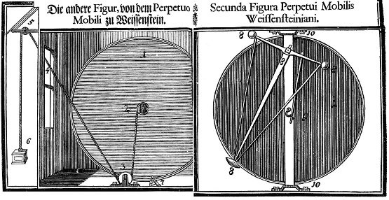
3) “Das Triumphans Perpetuum Mobile “- this was Bessler’s most professionally finished book. It was written in both German and Latin and this edition is a faithful reproduction of the actual pages of the original book. It also includes a full English translation at the rear. A number of drawings are included by the original author and these are said to contain a number of clues as to his machine’s workings.
http://payhip.com/b/DNUe
4) “Gruendlicher Bericht” - this was Bessler’s first publication, ostensibly produced by a friend although I think one can detect Bessler’s handiwork in places. This copy is also in the original German and includes a full English translation at the rear. It also includes the very first drawing which Bessler published and this also contains clues to the way his machine worked.
http://payhip.com/b/dahj
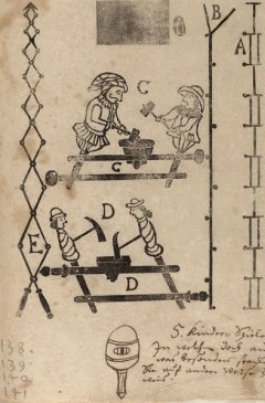
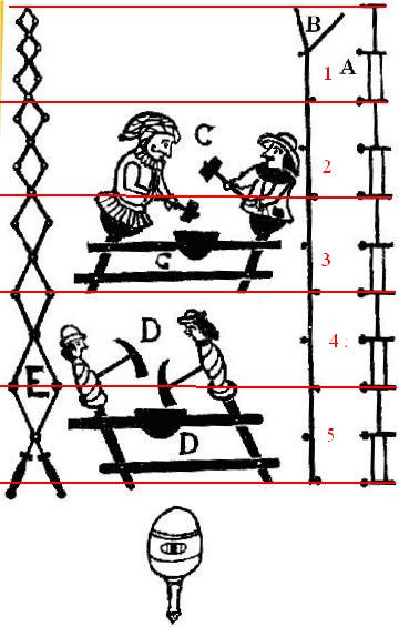
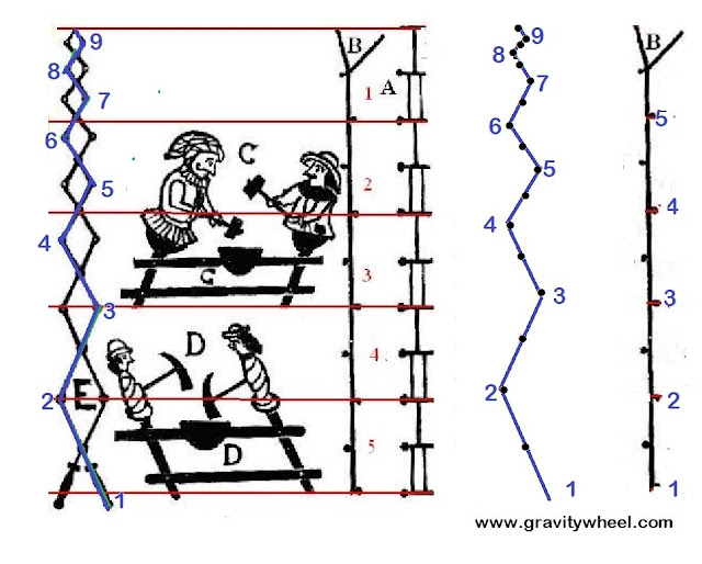
5) “Maschinen Tractate” - this was found in the Bessler’s possessions after his death, in the form of a number of pages (141) and which contained a message on the front of the volume which stated that he had removed the drawings which depicted how his machine worked but that some one with a penetrating mind could by studying several drawings ultimately discover the secret of its construction. I have reproduced the drawings as they were found. I included his handwritten notes with the best translation I could obtain, since the writing is very hard to read.
http://payhip.com/b/F8ZS
You can also read Christian Wagner’s two critiques of Bessler’s wheel at my main web site.
Copies of all the above books can be obtained from my web site at
Books available from www.free-energy.co.uk
Alternatively you can use the buttons in the lower part of the right side panel under the heading, ‘My Publications’, which also takes you to a payment page.
There are some excellent additional resources and a forum for discussion at the
Besslerwheel forum
The best German web site is at http://www.besslerrad.de/html/bekannte_details.html
That’s all. Of course some people prefer to continue their research into perpetual motion machines without referring to Bessler’s own efforts and I respect that, but for those who like to have the information relating to Johann Bessler aka Orffyreus to hand in an easily accessible format, the books detailed above provide a good digital resource.
It is common knowledge that Bessler left a lot of encoded information about how his wheel worked. I have published a great deal of information about these codes and you read details both here www.the orffyreus code.com and in my previous blogs.
JC