https://johncollinsnews.blogspot.com/2023/11/sharing-more-info-mt-138-139-140-and.html
This post contains some of my ideas about where and how Bessler intended to reveal the workings of his perpetual motion device, or what is generally referred to as Bessler’s Wheel. Without a working model this is speculation, but I believe it is based on some sound interpretation of the many clues and hints he scattered throughout his documents.
I’ve written several blogs about the ‘Toys’ page so this is my latest and best attempt to explain all of it.
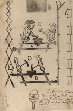
The figure below is from the original Maschinen Tractate, which is a name I coined for it because I originally thought that Bessler was referring to this collection of drawings in one of his letters but I think now he was talking about another project.
Underneath this original picture is the same figure cleaned up which is the one I’ll write about and explain what I believe is the true meaning of all the separate figures.
 )
)
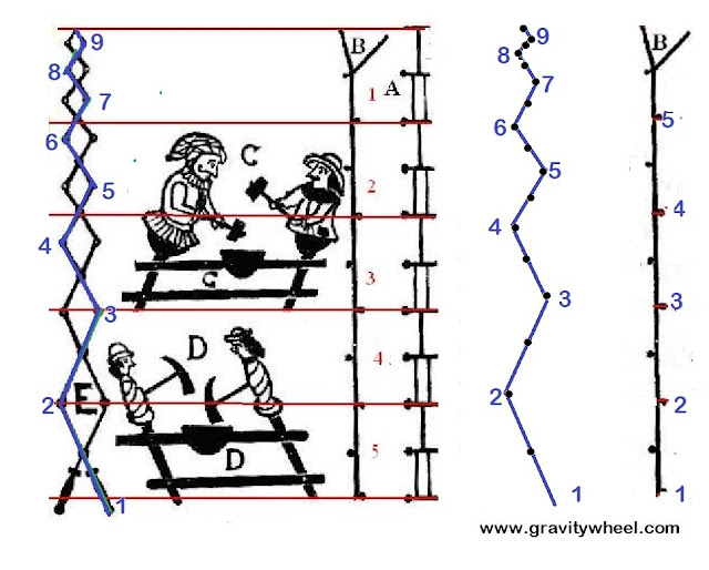
Notice first that items A and B can be split into five equal parts. This signifies that there are five mechanisms. Notice each figure in A looks similar to the two items C and D, this is to provide a hint that their actions very roughly mimic the actions of the actual mechanisms. Each part of A is linked to the next part with a length of rope.
Items C and D are each labelled twice. Both sets of figures show two figures working in pairs, which agrees with a statement to that effect by Bessler. The two C’s have arms but the two D’s don’t. The two C’s show two of the figures working in pairs before they have acted; the two D’s shows the same two figures after they have acted. This implies that C did the work so was active but D was acted upon and was passive. C lifted it’s paired mechanism and thus D was lifted. Item D has spirals which indicate that the figure is at a different angle to C, because if, for instance, C operates at the six o’clock radius the D is lifted from a different point on the edge of the circle.
It’s worth pointing out that he drew one of each mechanism but then added two D’s and two C’s to stress that the two figures were the same mechanisms working in pairs, but at different points in the rotation of the wheel.
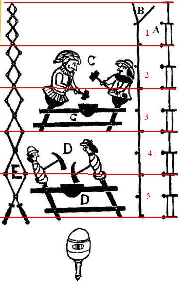
Item B is an interesting one and I only understood why it was drawn in this way a few months ago. The answer lies partly in item E. You can see in B that it consists of five straight vertical lines with one dot alternately on each side or, if you ignore the five separating lines, it’s a straight vertical line with those dots on alternate sides.
I’ll return to B in a moment, first let us examine item E. The items on the page are numbered 1 to 5, yet there are six, if you count the hand drawn spinning top. This looks like a late addition to me which might explain why he wrote 5. next to his scribble note. But as someone pointed out to me many years ago, the number 5. with its clearly drawn full stop or period indicates not five items, but the fifth item - the letter E. The scissor mechanism or storks bill.
Remember Bessler’s frequent use of alphanumerics, in this case his scribbled note in the Toys page, “5. Children's game in which there is something extraordinary for anyone who knows how to apply the game in a different way”, applies in particular to the scissor mechanism labelled E.
Now in another drawing which I’ll discuss in a later share, it indicates
that the scissor mechanism should be applied in a different way which looks like this one:-
In the above picture I have extracted items B and E because B shows which part of E you need to use. Notice the same dots are there in E but in B half of them have been removed leaving a single line. This shows the alternate swivel pins or joints holding the short lengths of metal at each end together. The middle of each piece of metal shows a pivot which allows it to rotate. If the figure B is accurate, and I’m sure it is, then there is one of these mechanisms in each fifth segment.
This is similar to the picture below which shows a simple mechanism used widely in organ building in Bessler’s time.
Also remember Bessler’s comment in AP, “ A crab crawls from side to side. It is sound, for it is designed thus.” This comment is a hint that this mechanism will work best in a horizontal position where there is no lifting required just side to side action.
The two short lines at the top end of the original version of B will be explained later but they indicate two positions of a short lever attached to the end of the zigzag line.
That’s all for now. More later.
JC