Friday 24 November 2023

Sharing Info MT 138, 139, 140 and 141- AKA — The TOYS Page

 https://johncollinsnews.blogspot.com/2023/11/sharing-more-info-mt-138-139-140-and.html

This post contains some of my ideas about where and how Bessler intended to reveal the workings of his perpetual motion device, or what is generally referred to as Bessler’s Wheel.  Without a working model this is speculation, but I believe it is based on some sound interpretation of the many clues and hints he scattered throughout his documents.

 I’ve written several blogs about the ‘Toys’ page so this is my latest and best attempt to explain all of it.

The figure below is from the original Maschinen Tractate, which is a name I coined for it because I originally thought that Bessler was referring to this collection of drawings in one of his letters but I think now he was talking about another project.

Underneath this original picture is the same figure cleaned up which is the one I’ll write about and explain what I believe is the true meaning of all the separate figures.


)

Notice first that items A and B can be split into five equal parts.  This signifies that there are five mechanisms.  Notice each figure in A looks similar to the two items C and D, this is to provide a hint that their actions very roughly mimic the actions of the actual mechanisms.  Each part of A is linked to the next part with a length of rope.

Items C and D are each labelled twice.  Both sets of figures show two figures working in pairs, which agrees with a statement to that effect by Bessler.  The two C’s have arms but the two D’s don’t. The two C’s show two of the figures working in pairs before they have acted; the two D’s shows the same two figures after they have acted. This implies that C did the work so was active but D was acted upon and was passive.  C lifted it’s paired mechanism and thus D was lifted. Item D has spirals which indicate that the figure is at a different angle to C, because if, for instance, C operates at the six o’clock radius the D is lifted from a different point on the edge of the circle.

It’s worth pointing out that he drew one of each mechanism but then added two D’s and two C’s to stress that the two figures were the same mechanisms working in pairs, but at different points in the rotation of the wheel.

Item B is an interesting one and I only understood why it was drawn in this way a few months ago. The answer lies partly in item E.  You can see in B that it consists of five straight vertical lines with one dot alternately on each side or, if you ignore the five separating lines, it’s a straight vertical line with those dots on alternate sides.

I’ll return to B in a moment, first let us examine item E. The items on the page are numbered 1 to 5, yet there are six, if you count the hand drawn spinning top.  This looks like a late addition to me which might explain why he wrote 5. next to his scribble note. But as someone pointed out to me many years ago, the number 5. with its clearly drawn full stop or period indicates not five items, but the fifth item - the letter E.  The scissor mechanism or storks bill.

Remember Bessler’s frequent use of alphanumerics, in this case his scribbled note in the Toys page, “5. Children's game in which there is something extraordinary for anyone who knows how to apply the game in a different way”, applies in particular to the scissor mechanism labelled E.

Now in another drawing which I’ll discuss in a later share, it indicates
that the scissor mechanism should be applied in a different way which looks like this one:-

In the above picture I have extracted items B and E because B shows which part of E you need to use. Notice the same dots are there in E but in B half of them have been removed leaving a single line. This shows the alternate swivel pins or joints holding the short lengths of metal at each end together. The middle of each piece of metal shows a pivot which allows it to rotate. If the figure B is accurate, and I’m sure it is, then there is one of these mechanisms in each fifth segment.

This is similar to the picture below which shows a simple mechanism used widely in organ building in Bessler’s time.  

Also remember Bessler’s comment in AP, “ A crab crawls from side to side. It is sound, for it is designed thus.”   This comment is a hint that this mechanism will work best in a horizontal position where there is no lifting required just side to side action.

The two short lines at the top end of the original version of B will be explained later but they indicate two positions of a short lever attached to the end of the zigzag line.

That’s all for now. More later.

JC


Wednesday 25 October 2023

Johann Bessler’s Use of Alphanumerics.

In addition to his search for the solution to designing and building a perpetual motion machine Johann Bessler was also fascinated with the subjects of numbers, alphabets, alphanumerics and chronograms.  This obsession might have been heightened by his visit to Prague where he learned about codes and ciphers.

He used his name to encode information about the number five and fifty-five.  Potentially this clue pointed to the pentagram and/or chapter 55 of his second book Apologia Poetica(AP).  This chapter is full of coded stuff which I go into more on my websites at www.theorffyreuscode.com and www.orffyreus.net

His first two illustrations, one in Grundlicher Bericht (GB) and another version in Das Triumphans…(DT) include a lot of numbered parts.  Using just the numbers 1 - 24, he obtained a total of 660 which divided by 12 gives 55.  Why divide by 12?  Because Bessler cleverly embedded a clock in the same two drawings showing the 12 hours. This is the one from DT.

By drawing the lines of perspective within the illustration you can find a clock.  This is confirmed by the eight o’clock line which includes two items numbered eight. Taking the 660 and dividing it by the clock’s twelve hours we obtain 55 

His next illustration in DT was the Die Andere and Secunda Figua which was one illustration in two parts.  He uses just the numbers from 1 - 10 which totals 55. Addingh all the numbers used on the left side totals 28, but those on the right add up to - you guessed it, 55!  


The last illustration was of his wheel driving an Archimedes screw pump and included labelled parts, but this time he used the alphabet, labelling parts from ‘a’ to ‘t’, plus one part labelled 10, although it also looked like the letter ‘w’.  I checked the list of numbered parts and it did show a 10 and not a ‘w’.  Why not use the letter ‘u’ to follow his use of the letter’u’?

Maybe by using Bessler’s favoured Caesar shift system, we find that ‘w’ is equivalent to the letter ‘j’, ‘j is the tenth letter.  So why? I think it was a hint to read the alphabetic in this figure as both alphanumerics as well as the atbash. Any way the totals are as follows.


There are 39 numbers totalling 355. The letter ‘e’ is as usual missing from the left side, but that was how he highlighting the number. Adding the 5 to 355 to give 360,  and brings the number total 40 - so 20 for each half.  360 divided by 20 equals 18, the basic pentagonal number, snd of course 360 divided by the missing 5 equals 72, one fifth of the pentagon.

I could go on because there’s so much more, but although this is interesting it’s just another pointer to the number 5 and 55, which can point to the need for five mechanisms, and/or chapter 55 in his Apologia Poetica which has the 141 Bible references, and for a look at my attempts to decipher it see my web site at http://www.orffyreus.net/.      

More hidden, more useful,  information to follow.

JC


Monday 2 October 2023

More Information Hidden In Plain Sight

 I have mentioned the “craftsman phrase” on my blog, several times and I suggested that it meant that the fallen weight only needed to be lifted 30 degrees.   Below is another illustration from Bessler’s “Das Triumphant Orffyrean Perpetual Motion” (DT) which repeats the same information graphically.  This one is ingenious.

As usual I have included a pentagon because it’s a vital ingredient in Bessler’s wheel and as you’ll see, it’s presence is implied. Another feature of all the illustrations in DT is his use of the numbering of each part. The first picture in DT, which shows the Merseburg wheel, includes the numbers from 1 to 24, which totals 660.  He embedded a clock within the picture, 660 divided by the 12 hours equals 55.  Yes there it is again, his recurring number 55. You can find several references to the use of the clock in my blog, just use the search box at the bottom of the right side panel.

The same applies in the following illustration. He only uses the numbers from 1 to 10, but added together they total 55 - there’s definitely a theme here! - and when all the numbers in the right hand picture are added together they also total 55.

In the illustration below, I have filled in the pentagram in red. Originally the two drawings were on adjacent but separate pages. In the crease of the binding there were two rows of black and white lines allowing one to push together the two pages to make a perfect join at their two black borders as in the illustration.

The red line extends the upper right side of a pentagram in the left hand drawing, to coincide with the centre of the right circle. The triangle has a bottom angle of 30 degrees, and an upper right angle of 72 degrees and the remaining one, 78 degrees to complete the triangle.  In a pentagram that triangle has two 72 degree angles and one 36 degree but in this case the small bottom angle measures 30 degrees so the upper right one is 72 degrees which means the remaining one has to be 78 degrees.

Notice that in the the left picture the wheel contains horizontal hatchings and outside of the wheel they are vertical.  In the right picture the hatch marks are vertical and there are none outside the wheel.  The left picture is cut off on the right side. It looks as though we are meant to slide the right one over to the left, above the left one.

 
The elliptical or ovoid shape on the bottom of the triangle is designed to tell us to rotate the whole pendulum around it.  I realised this was necessary because of the three lines coming out of it seemed to suggest this as a possibility. and because we know the 30 degrees is the size of the lift required in Bessler’s connectedness principle.

In the next illustration I have copied across the large triangular pendulum and tilted it so that the centre of the three verticals coming out of the ovoid are located on the centre of the left side wheel and aligned with the hatching lines  The two weights identified with red circles fit precisely on the rope, showing the 30 degree lift. The blue lines demonstrate the position if we ignore red circled weights, which I think shows that they shouldn’t be ignored.  


The 30 degrees indicates the 30 degrees the weight must be lifted. As was usual with Bessler’s clues, he provides confirmation that the interpretation is correct, by including an additional clue. So the 72 degree angle in the upper right of the triangular pendulum suggests the presence of a pentagram and the top bar on it, once rotated, aligns with the extension of the pentagram from the left drawing. In confirmation that both drawing should be taken together, using all the numbers used to label the parts, 1 – 10 total 55. 55 is the number that Bessler uses everywhere to point to his five mechanisms, via the pentagram.

JC

                                                                 Copyright © 2023 John Collins. 

Saturday 23 September 2023

Bessler’s Gravitywheel - The Next Step

I said I wouldn’t show any pics of previous builds, and in fact there aren’t many left but this one (slightly out-of-focus!) was handy.  It was taken in 2016 just before moving house.  You can see the familiar five mech set up.  (Best ignored!)


There follow a few examples of Bessler’s ‘hiding in plain sight’ technique.  The picture below appeared in Johann Bessler’s Das Triumpant Orffyrean Perpetual Motion book. It was a second version of the original design which was included in his first booklet, Grundlicher Bericht. There are a few differences between the two versions but mostly I use the second drawing to illustrate my finds.

In the picture note the six columns or pillars, not including the main one supporting the wheel.  Two are drawn in three dimensions, numbered 4, but the other four, numbered 12, are two dimensional and their tops are indicated by my short red lines. The latter act as datum points. The two on either side of the central pillar provide pointers to enlarge the circumference of the wheel. 

The green line which is extended from the left side of the picture and aligns with the centre of the wheel, indicates one of two possible diameter lines. Two lines each drawn 18 degrees apart from the lower end of the green line conform to Euclid’s pentagram construction advice.

Confirmation is provided by the other two datum points which align with the purple 18-degree line and the hatching lines on the wheel and the capital letter M. If you draw a line similar to the purple line but aligning the left sides of the two red lines, the alignment is perfect with the hash marking in the wheel. I think that both lines finish in the same place but obviously they can’t both do that as well as align perfectly with the hash markings.

Notice that the outer circle now includes the left side of the ‘T’ pendulum, the point of the padlock and touches the bottom and right edges of the rectangle.

Below is a pic of how I worked out the correct position for the two circles


You might think I drew the inner circle first, placed the pentagram within it with five radii extended to the outer circle. But if you do that, you don’t know exactly where the inner circle will be so you have to draw in the outer one first before you can calculate exactly where the inner one will be. To calculate remember that all angles are multiples of 18.   Remember that Johann Bessler actually altered his forenames to include the number 5 and 18.

Below I’ve included a picture of my wheel’s baseplate upon which the mechanisms will eventually be attached. The pentagram is drawn in and you will notice an inner circle is included.  It is upon this circle that the five pivots are positioned. The drawing is not 100 per cent accurate but will suffice.

www.gravitywheel.com

The next bit is to drill the pivot holes, ready for the the five pivot stubs.  The levers are mounted on the pivots.  Their range of movement of each weight covers an arc of 90 degrees. There is more to be taken into account here and it’s not visible in the above picture. As the build progresses I’ll show more.  Although I’ve shown this configuration before, it still lacks a number of details so far.

For more evidence of the ubiquity of hints about the importance of  the number five visit my website at The Orffyreus Code

JC

Thursday 14 September 2023

Bessler’s Gravitywheel - first steps.

The configuration of the build that I will share here is based on my interpretation of many of the clues Johann Bessler left for us.  Sometimes I might not show how I arrived at a feature of the design because it would take up too much space to explain and I think most people would prefer to see the progression of the build.  Having said that I will show some details to help understand why a particular part of the design is the way it is.

As for the clues, one of the clearest indications that Johann Bessler left coded information lies in his use of a pseudonym, Orffyreus.  This device was a well-known system of coding, known in ancient Hebrew times as atbash or in later times as the Caesar shift, it involved alphabetic substitution.  Using this simple code, Bessler changed his name to Orffyre which he then Latinised to Orffyreus. Why use such a simple easily identified code?  His purpose in adopting a pseudonym was to draw attention to the possibility of further coded information.  I followed the hint and found numerous examples of codes and latterly I found the really useful information which was designed to reveal his secret to anyone with the determination to follow the path he laid in various places.

There is much that still eludes my amateur skills in this field but I’m certain that once his secret is exposed to the world, his other ciphers will be broken and more information will be published by those whose expertise puts my own efforts in the shade.

This subject has been discussed numerous times on my other websites, see the links in the side panel. My publications are also listed there.

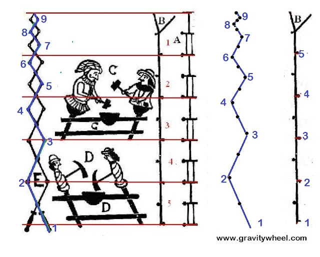
The most obvious clue obtained right from the beginning is the importance Bessler attributed to the number five, and through a process of deduction from many other clues, I found that his gravity-enabled wheel had five compartments each containing a single mechanism; that each fifth segment contained one mechanism and one weight; each weight being of equal size - and that the mechanisms operated in pairs.

Each mechanism was paired with its adjacent one, and as a weight fell, it lifted the previous fallen weight back to its former position easily.  A clue to this action lies in one of Bessler’s more obscure clues.

He will be called a great artist if he can easily throw a heavy thing high and if a pound falls a quarter it will shoot up four pounds four quarters.

alternatives to “shoot up” are given as leap, bounce, jump.

Note that within the quote he mentions that there are five weights, one plus four, and each one is equal to one pound, and one pound falls a quarter.  
NB When he says one pound falls 90 degrees it will lift four pounds four quarters, he means as each pound falls it lift each of the other pounds 30 degrees, in turn.
In the first part the word ‘quarter', referred to, not just 90 degrees but also to a clock.  In the second part the word ‘quarter' also refers to a clock but this time he has used the words ‘four quarters’. ‘Four quarter’s equals ‘one whole hour’.  Each hour on a clock is divided into 30 degrees, so the words ‘four quarters’ meaning ‘one hour’ as used here equals thirty degrees.  To paraphrase Bessler’s words, “a great craftsman would be he who, as one pound falls 90 degrees, causes each of the other four pounds to shoot upwards 30 degrees.”
This looks unremarkable but it will become apparent why this worked, it and certainly made the weight “shoot upwards”. He provides confirmation of this fact in two other places, “hidden in plain sight”.
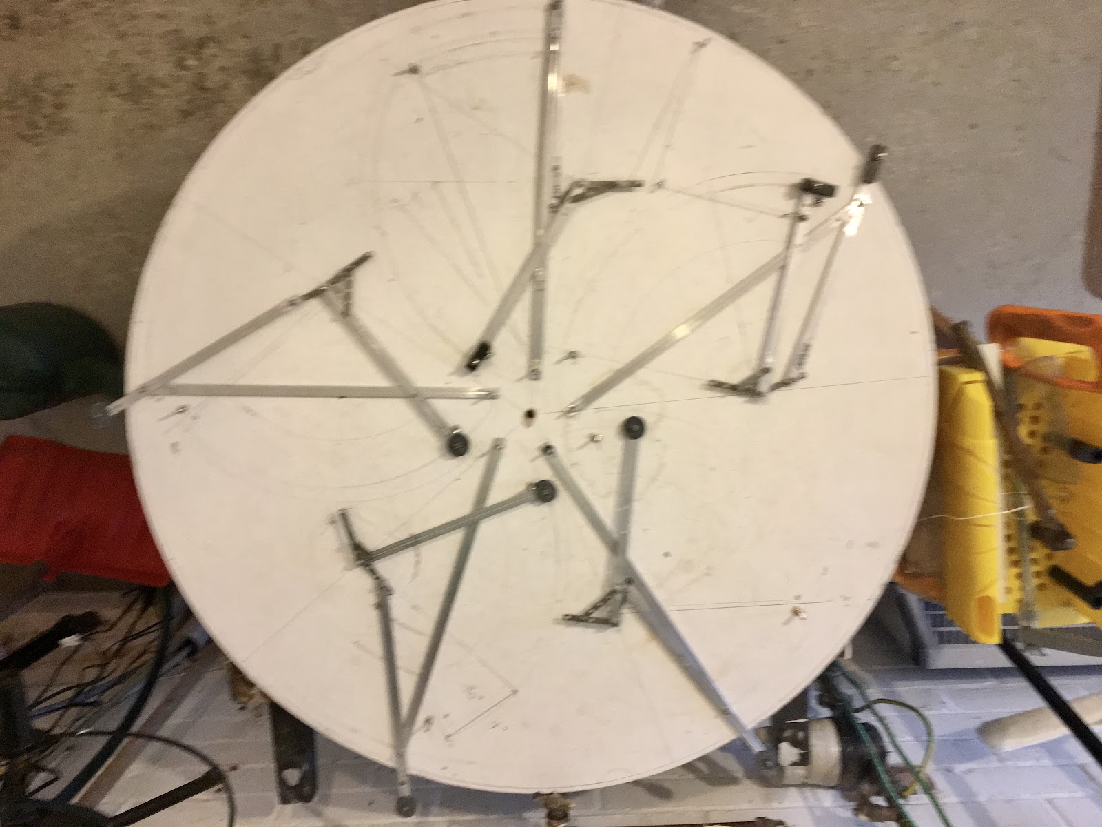
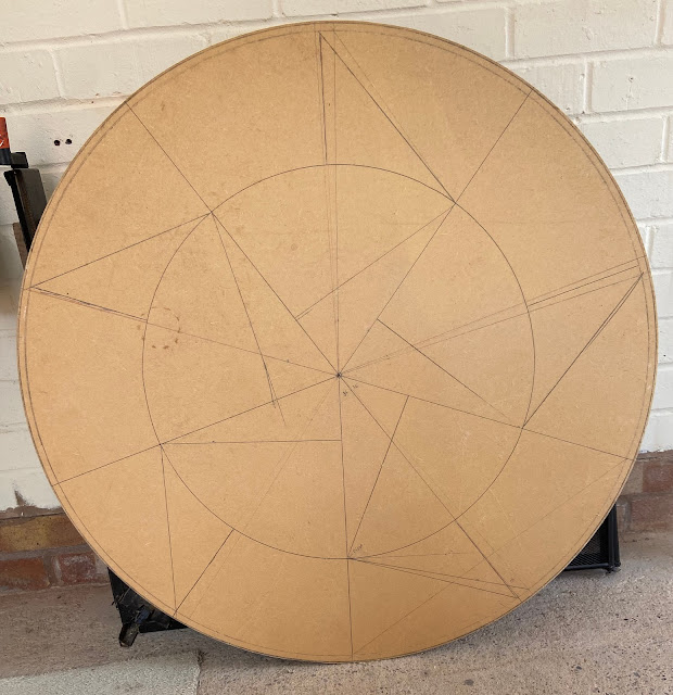
So we need a configuration with five equal segments, as per a pentagram. We need to know where the pivots from which the weighted levers are suspended.  We need to know their arc of travel and we need to know how each pair of mechanisms were connected. Plus we need to know what makes a design similar to this different to anything any of us have seen before.
Bessler showed us how to find the position of the pivots - but like many of his clues again, “hidden in plain sight”.  I will reveal several other hidden clues over the next few blogs.  Progress on my construction will be reported occasionally as it develops.
JC

Monday 11 September 2023

The Legend of Johann Bessler’s Wheel.

This is my new blog, beginning today.  I intend to post details of my reconstruction of Bessler’s wheel here.  For those of you who are unfamiliar with the legend of Bessler’s wheel, or as it is sometime called the wheel of Orffyreus, (Orffyreus was his pseudonym) I am posting below a brief account of the story of Johann Bessler.

Before that I must tell you that many people believe Bessler’s claim to have succeeded in building a perpetual motion machine was genuine.  It was driven by falling weights so, it is claimed, it depended on the force of gravity.  I discovered that Bessler had left instructions showing how his machine worked, cleverly encoded in several different ways.  I have managed to decipher much of his hidden information, and it is this which I shall be publishing here.

The Legend of Johann Bessler’s Wheel.

On 6th June, 1712, in Germany, Johann Bessler (also known by his pseudonym, Orffyreus) announced that after many years of failure, he had succeeded in designing and building a perpetual motion machine.  For more than fourteen years he exhibited his machine and allowed people to thoroughly examine it.  Following advice from the famous scientist, Gottfried Leibniz, he devised a number of demonstrations and tests designed to prove the validity of his machine without giving away the secret of its design.

After more than thirty years he died in poverty.  He had asked for a huge sum of money for the secret, £20,000 which was an amount only affordable by kings and princes, and although many were interested, none were prepared to agree to the terms of the deal. Bessler required that he be given the money and the buyer take the machine without verifying that it worked.  Those who sought to purchase the wheel, for that was the form the machine took, insisted that they see the secret mechanism before they parted with the money. Bessler feared that once the design was known the buyers could simply walk away knowing how to build his machine and he would get nothing for his trouble.
This problem was anticipated by Bessler and he took extraordinary measures to ensure that his secret was safe, but he encoded all the information needed to reconstruct the machine in a small number of books that he published. It is well-known that he was prepared to die without selling the secret and that he believed that post humus acknowledgement was preferable to being robbed of his secret while he yet lived.

The information to be published here will include a video of my reconstrction of Bessler's wheel revolving.  Another video will give a brief account of the codes and where they are.  A book detailing all of the codes and their meaning will follow.

JC

Tuesday 5 September 2023

Gravitywheel.com

This new blog is an addition to my other blog which has been running for more than thirteen years.  Here I intend to post details of my current construction of Johann Bessler’s gravitywheel.  It is based on some of the clues I’ve deciphered.  If it works I will share the successful design here and in many other places.  If it fails I will still share everything I know because even if my build fails, I have deciphered many of Johann Bessler’s clues and codes and these may help someone else to achieve more than I have.

Who is Johann Bessler?  What is this Gravity Wheel?

Well, for answers to both questions, visit my other blog at https://johncollinsnews.blogspot.com/

You can also buy the five books I’ve published by following this link, attached to the above one

https://johncollinsnews.blogspot.com/p/johann-besslers-books-and-biography.html

There you can read all about this extraordinary man who built a so-called  Perpetual Motion machine more than 300 years ago in Germany.  He offered it for sale and provided as much proof as possible that  it was real, without actually revealing the internal workings. He offered numerous demonstrations, allowed every visitor the option to climb all over it check if it was being driven in some secret manner.  His demonstrations included raising a 70 pound weight up and down the side of the building in which the machine was situated.  He provided an alternative set of bearings to which the machine could be transferred, both sets were available for inspection before  and after.  He conducted a long term test of 54 days under lock and key.  

He also allowed just one person to see the interior of the machine, his name was Karl, the Landgrave of Hesse-Kassel, a highly respected man of impeccable reputation.  He was able to view and understand the workings of the machine and issued a declaration that  Bessler’s wheel, as it has become known, was genuine, it worked and was in fact quite simple.  So much information is available today, it is only a matter of weeks before his secret is revealed.

JC